

Inventor 101 - Assembly/Joint Constraints
Do you know the difference between Assembly Static constraints and Joint constraints?
Most users know and use the static Assembly constraints to remove all 6 degrees of freedom in their assembly models, but what about Joint constraints?
Joint constraints, just like static constraints, remove degrees of freedom, but at the same time, allow for specific movement(s) of the parts. This comes in extremely handy during the design process and can be used to validate your design ideas of how the assembly will react in the real world.
The use of Joint Constraints allows you to evaluate, demonstrate and analyze your designs. Some of the methods you can use Joint Constraints for are:
· Simulate mechanical motion with a Drive Joint constraint
· Validate/Analyze component collision instances
· Simulate an assembly’s kinematics with Dynamic Simulation

Step #1 - Select the Joint command
Selecting the Joint icon on the ribbon menu for Relationships, brings up the Place Joint menu:

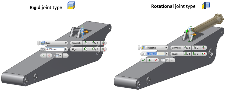
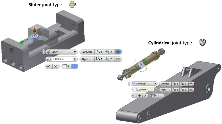
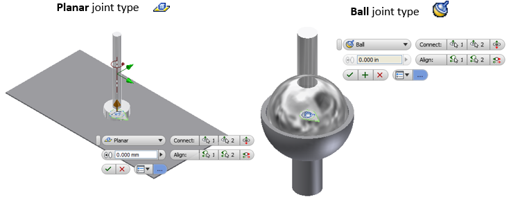
The Joint constraint type options are found in the drop-down for the “Type”:
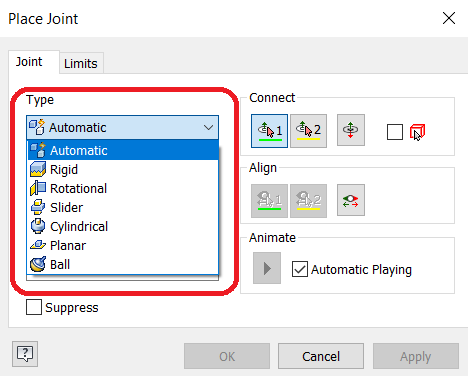
Each Type removes various degrees of freedom (DOF) allowing for a specific movement.
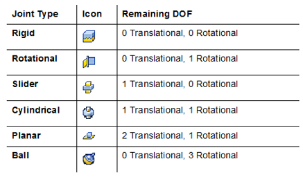
Step #2 – Select the Joint Type Desired (Ref above)
The Automatic Joint type is the default. This option permits Inventor to assume the joint type based on the selected references (No worries, if the wrong joint is assumed, it can be changed).
Of course, the user can also manually select the joint type desired instead.
Step #3 – Selecting the References
The first reference is automatically assigned to the (First Origin) field

The second reference is automatically assigned to the (Second Origin) field

The user is able to select faces, edges, or spherical geometry as references.
Hover the cursor around the entity to activate the required Joint Origin shown by the green dot glyph.
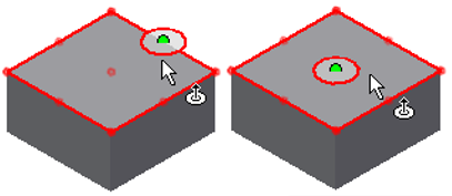
Face Reference
When a rectangular face is selected, the active point can be on any of the corners, on the midpoints of any edge, or at the center point of the face. The location of the cursor when selecting defines which point is assigned.
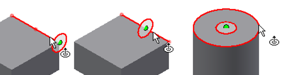
Edge Reference
When a straight edge is selected, the active point can be on either end or at the center point of the edge. The location of the cursor when selected defines which point is assigned.
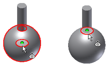
Spherical Reference
When spherical geometry is selected, the active point is at the center of the geometry or at points where geometry intersects with the surface of the sphere. The location of the cursor when selecting defines which point is assigned.
Notes:
• The order in which references are selected can affect the orientation of the model.
• The first component selected is the component that is going to be moved when the joint is finalized.
• If the first reference selected is on a grounded component you are prompted that a grounded component is selected to be moved.
• Moving a grounded component does not remove its grounded status.

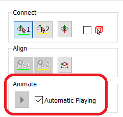
Once references have been defined, the components automatically move into position and play an animation indicating the type of motion (if the Automatic Playing check box is selected in the Animate section).
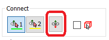
Click the Flip Component in the Connect area to flip the component’s orientation
The Alignment references are automatically selected based on the First and Second Origin references. To change alignment, you can flip or assign new references.

Some examples of selected references:
Step #4 – Assign a Gap value, if required
A Gap value provides the flexibility of joining the reference points at an offset.

Step #5 – Assign Limits, if required
Setting limits will define a specific range of motion. Select the Limits tab in the Place Joint dialog box, then enter the values in the Angular and Linear areas.

Step #6 – Complete the Joint
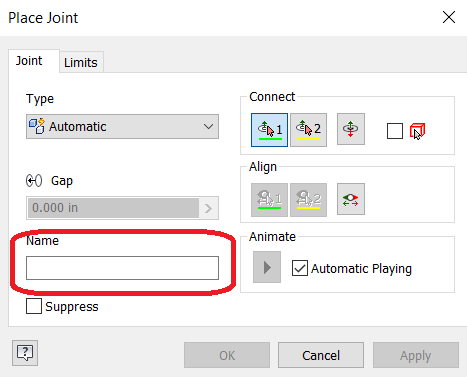
Enter a name for the joint in the Place Joint dialog box. Click OK.
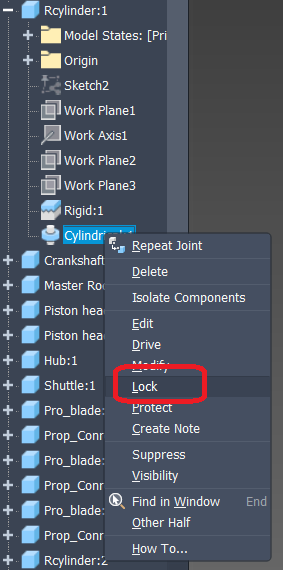
The Lock option maintains the current position but does not disable the DOF. A locked component cannot be moved but moves if connected components are moved.
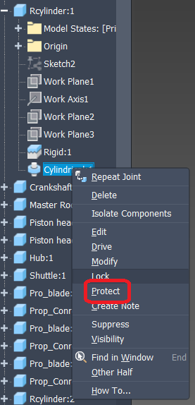
The Protect option warns if relationships violate the degrees of freedom.
Note: You can use the static Constrain or Assemble options to add additional constraints between components, as required.
Step #7 – Editing Joints, if required

· To Modify values: Double-click on the joint name or right-click and select “Modify”
· To Edit references: Right-click and select Edit to open the Edit Joint dialog box and mini-toolbar
· To Review Relationships: Use Free Move and drag to show the relationships
· Right-click on the glyphs to Delete, Edit or Suppress
· Use Show Sick to review failing relationships:

This is just a snapshot of using the Joint Constraint command. Have you used them? If so, how and what did you find? Did it save you from a major design flaw?